RFID based Front Door Lock
Main Idea / Purpose
Instead of using physical keys to manage access to the space it would be much easier to manage RFID card keys. This is mostly for the cases when a member moves away, stops paying their payments, or otherwise is no longer a member. Instead of changing the lock and giving out all new keys or tracking down the member to get their key back we can just take the unique RFID out of the “Whitelist” stored in the door lock computer. It could even be fully automated based on the data in our member/payment tracking system, Seltzer CRM.
#Benefits The use of physical (brass) keys is expensive, time consuming and difficult to manage. Also it does not provide utilization information. Who used the space when. This is valuable information for the management of Melbourne Makerspace. Future expansion allows the system to control access to complex machines. Allowing only authorized individuals the use of selected machines. It has been suggested that this same system could be expanded to the vending of snacks and parts.
#Considerations The inside door will retain the combination lock. In the event of an ACON failure, only the COMCEN is at risk.
The system must provide an emergency override magnet disable switch that deactivates the mag-lock.
The system must provide an EXIT request button proximal to the door. Reachable by someone in a wheel chair.
Secure emergency mag-lock deactivation from outside the building must be provided.
Light that indicates the mag-lock is active.
Operations should be secure. The usage of WIFI for internet access is not recommended.
The system should monitor the door open/closed status.
A doorbell will be needed to promote visitor access.
Project Concept
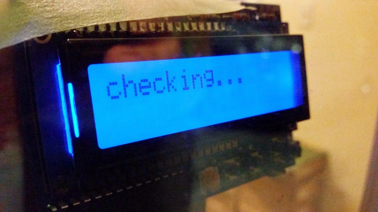
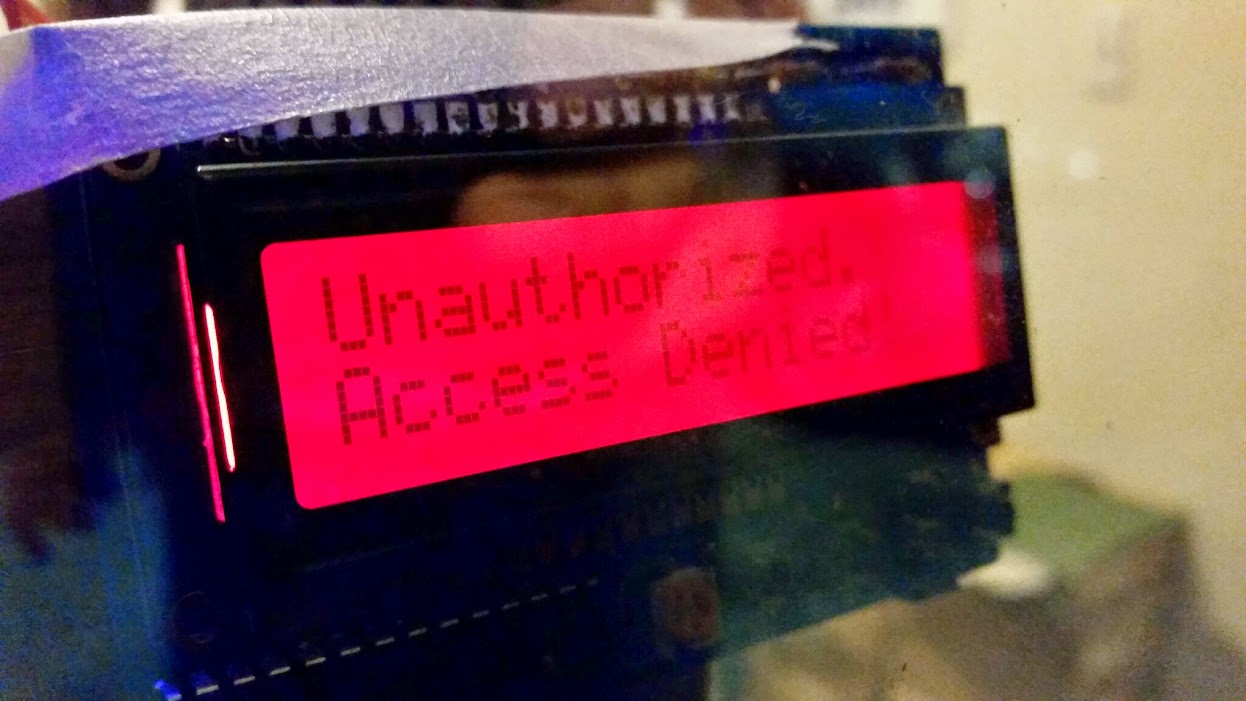
We will use the RFID reader from Jaycon Systems, a Raspberry Pi, and a servo based deadbolt lock (or magnetic lock). A REST (Representational State Transfer) endpoint will be created for Seltzer CRM that can be polled by the Raspberry Pi nightly to get the latest Whitelist of RFIDs assigned to members that have not lapsed on payments. The Raspberry Pi would then store and overwrite this Whitelist on its SD card. When the RFID detects a swipe it checks if that ID is in the Whitelist on the local SD card. If it is, it throws open the deadbolt and allows entry. If not in the Whitelist it would then query the REST web service with the scanned RFID serial to check the authoritative data base. If neither way produces a match, it could tell a buzzer to make a low “uh oh” sound and light up a red LED or display a message on an LCD screen like “access denied” or similar.
#Project Name
The systems is originally designed to control access to Melbourne Makerspace. It was therefore given the name ACON.
How it works
Software
All of the source code for both the PHP that runs on the Seltzer server and the Python that runs on the Raspberry Pi can be found in our GitHub repo here: https://github.com/MelbourneMakerSpace/RFIDLock
The Seltzer CRM database will hold each member’s key “serial number”. The is the authoritative data base. Seltzer also has a way for treasurer to add payments for each member as it comes in. It also has a Paypal import option to import all the Paypal payments once a month.
Josh wrote a PHP REST web service script that runs on the same server as Seltzer that queries the DB to determine if a user is allowed access or not, based on the serial number of the card scanned by the RFID reader. For now, it does an SQL query that checks if the key owner has made a payment in the past Forty Five (45) days. This can be changed to 60 or even 90 days if we as needed.
Josh also wrote two python scripts:
RFIDValidator.py = contains a function called validate, that takes the scanned RFID and passes it to the URL of the PHP REST web service to return TRUE if that function returns true, FALSE otherwise. You will need to make sure to install the python “requests” library before this will run:
Instructions for installing python requests library
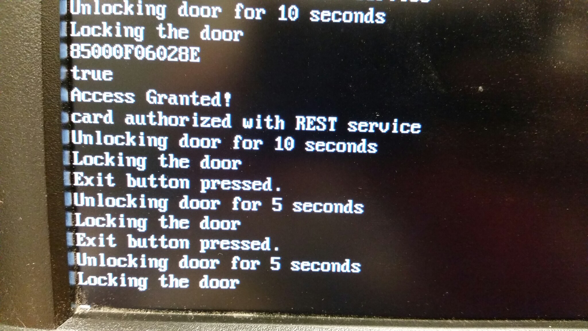
RaspberryPiRFID.py = reads the RFID card reader over the RPi GPIO UART serial pins to get the serial number from the scanned card. It then checks a local Whitelist of valid RFID serial numbers, then uses the validate method above to check if the card is valid via the REST service. It will then trigger a relay switch to actually open the physical door lock using another pin on the GPIO. Finally it will also listen to a button press on another pin on the GPIO for the “EXIT button” to immediately trigger the relay to unlock the door from the inside.
To make the script run automatically when the Raspberry Pi boots up add this to cron:
@reboot python /home/pi/RaspberryPiRFID.py & Note: to edit cron use this command:
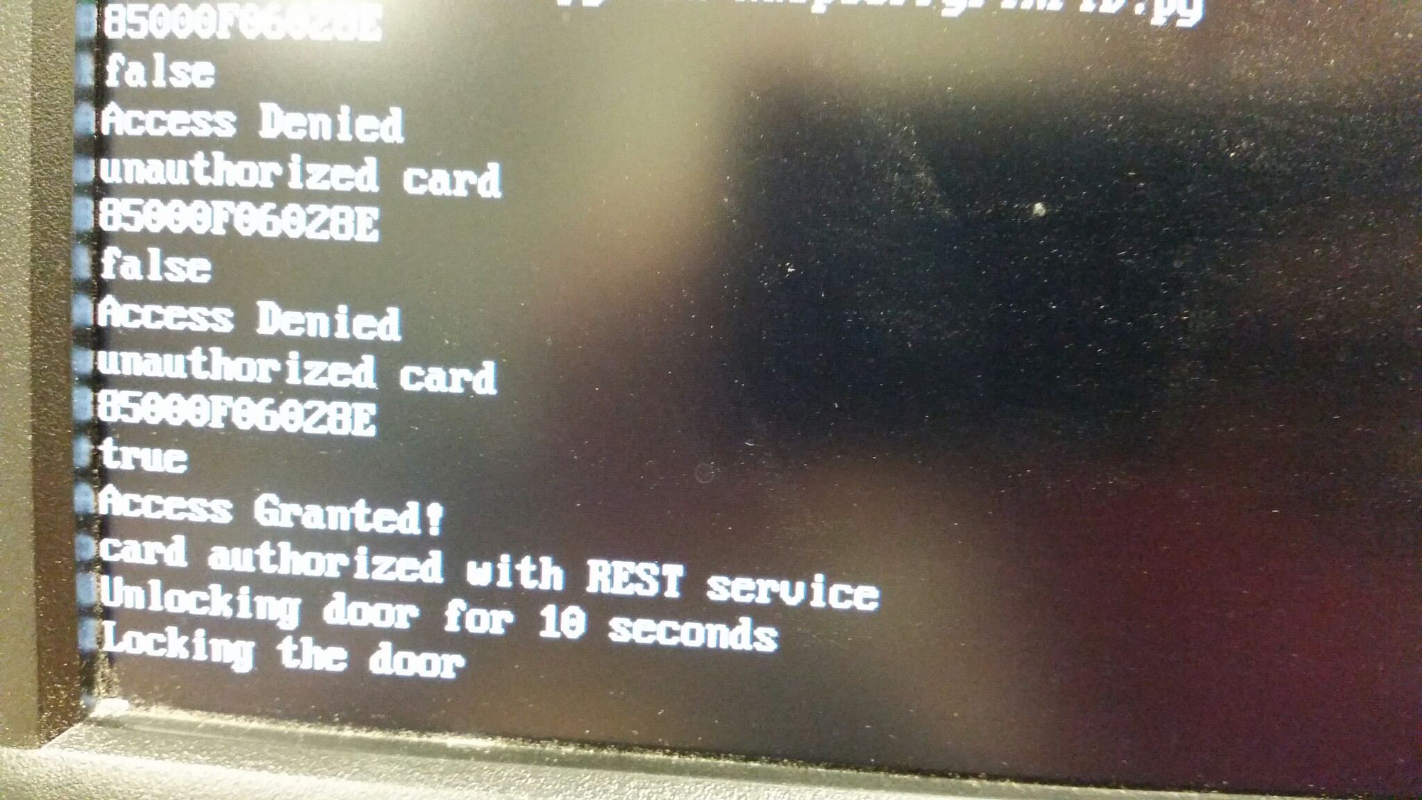
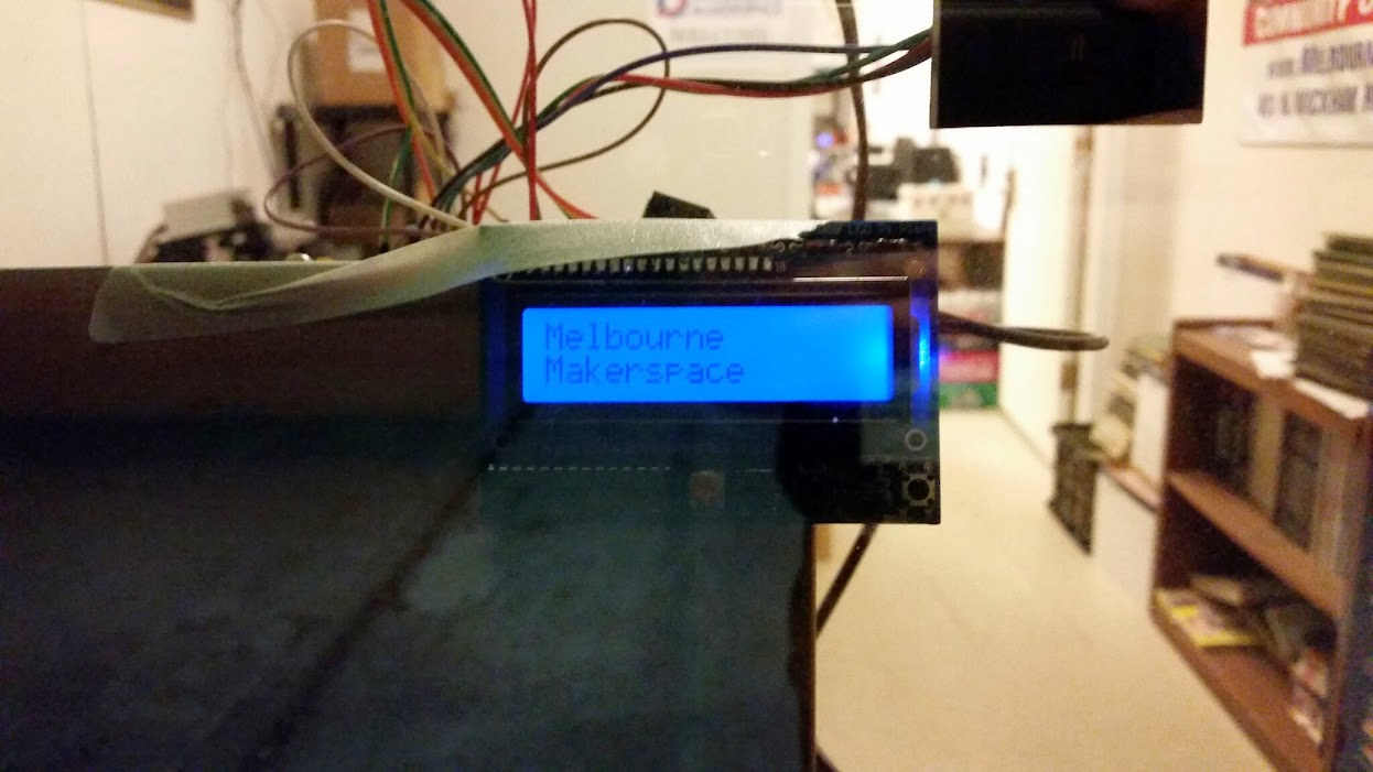
sudo crontab -e To see the RFID being scanned, along with messages like ACCESS GRANTED and ACCESS DENIED, etc. as well as to see the number of a new RFID card given to a new member we’ll add the Adafruit LCD display from Jaycon Systems.
We can use the sample code and instructions here to add to our existing code to write the messages we want to it:
Adafruit Learn: Raspberry Pi LCD display
Hardware
The ACON system is housed in an 14-in Modular Enclosure with Screwed Cover purchased from LOWES.
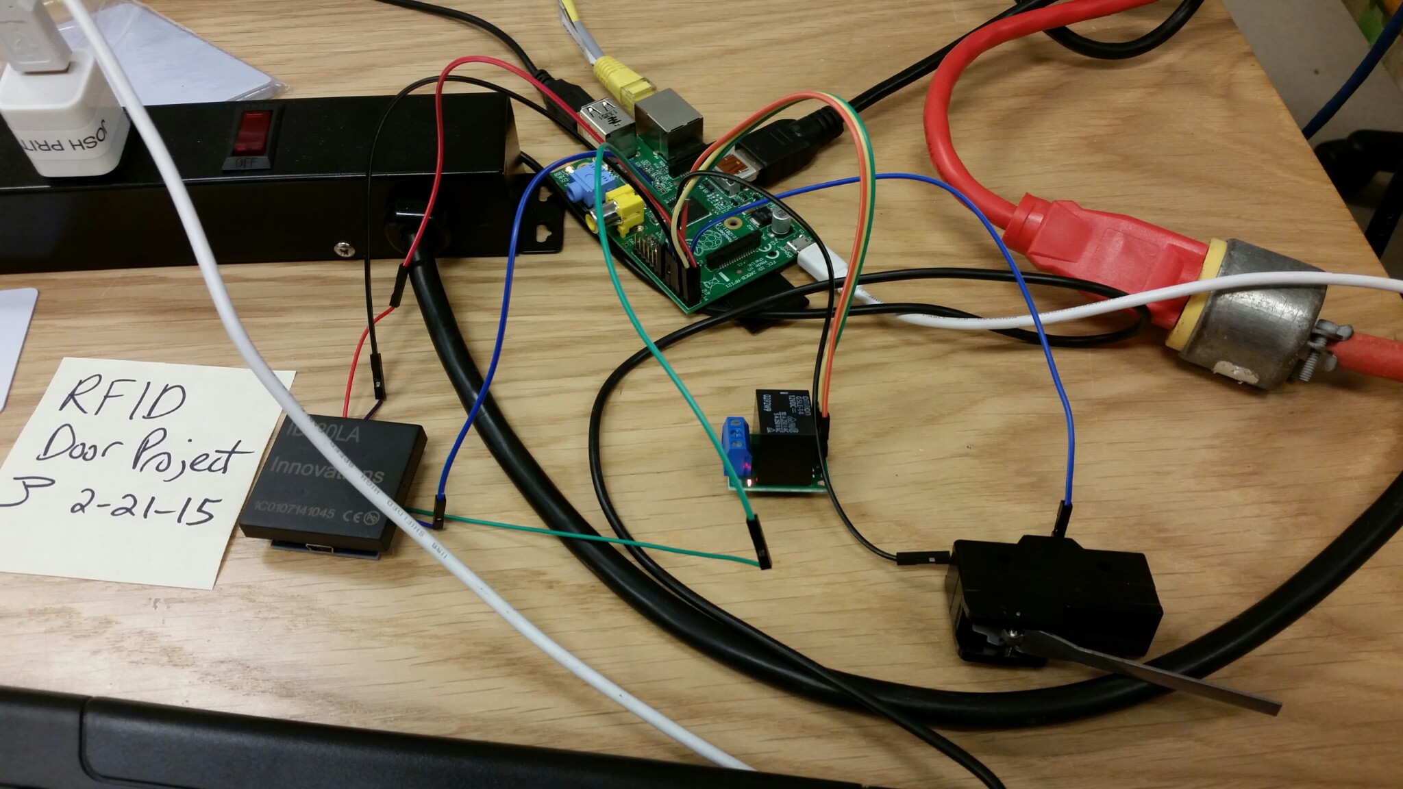
An ATX power supply was modified to always be on (push button not required) and the connectors were removed and replaced with wire lugs and barrier strips.
The power supply. Raspberry Pi, relay, RFID reader, 2X16 character display, switch, button and light were mounted in the box. Then wired up. The box was then mounted to the aluminum door frame. The mag-lock and mating plate were attached to the door and the door frame. Then wired to the ACON box. The RFID reader and 2X16 display were attached to a plastic sheet and that was attached to the back side of the box. This places the RFID reader and display next to the glass. No part of the system is exposed to weather.
Interconnections
Using the RFID reader from Jaycon plus the breakout board, connect the 3v3 pin 1 of the RPi GPIO to the VCC pin of the RFID breakout (it will scan and beep at 5v but will not operate the serial level at 3v3).
Connect the ground pin of GPIO pin 6 to the GND pin of the RFID breakout.
Connect the UART Tx GPIO pin 8 to the Tx pin on the RFID board (yes, Tx to Tx).
Connect the UART Rx GPIO pin 10 to the Rx pin on the breakout.
Connect the trigger pin of the relay switch to pin 7 of the GPIO. Connect the exit button to pin 11 of the GPIO.
To connect the LCD screen:
Connect female to male jumpers from the GPIO pins on the Raspberry Pi to the corresponding pins in the female header where they would connect if the screen were to be placed directly on top of the Raspberry Pi.
Connect one of the 5v pins (pin 2 or 4), one of the ground pins, and both of the I2C pins (3 and 5). These four pins are all that the screen needs to function!
Here’s an image of the pinouts for reference.
The EXIT button is used to unlock the door from the inside of the room.
The relay switch is connected to whatever used for the physical lock - Magnetic lock, servo driven deadbolt, etc.
Relay switched common (C) is connected to power supply +12 VDC. Relay switched normally closed (NC) is connected magnet enable/disable switch.
Magnet enable/disable switch connects to +V mag-lock.
Mag-lock 0V connects to power supply return (ground).
To connect the Raspberry Pi:
Connect RJ45 cable to live ethernet hub with access to internet.
Connect USB cable with lugs to +5VDC and 0V.
A monitor and or keyboard may be connected if desired.

Added new LCD screen: #Contributors Josh Pritt: Software and concept. Dale Noble: Hardware and installation Tony Belomo: Hardware, Software, installation and concept. Since the new card access system is now in progress; It behooves us to ensure it remains secure over time. Additionally, security issues in the IoT is currently a hot topic in computer security; it’d be good to get members interested in best practices and advanced analysis of in embedded security. To that Shawn is proposing a bug bounty for finding security vulnerabilities in the card access system. Bugs eligible for payout shall must meet the following requirements: The following members have pledged money toward the bounty:


 The RFID card reader and display are mounted to the white box next to the glass.
Bug Bounty (PoC||GTFO)
Prize
Other spaces using our RFID Door Lock